Cảm Biến Nhịp Tim và Oxy Trong Máu MAX30100
Mục lục
Giới thiệu
Module Cảm Biến Nhịp Tim và Oxy Trong Máu MAX30100 trên trang chủ
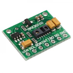
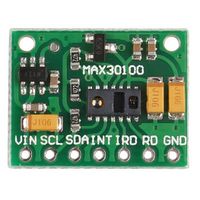
Module tích hợp Cảm biến MAX30100 của hãng Maxim, có khả năng đo được nồng độ Oxy trong máu và nhịp tim. Đó là một cảm biến quang học, nó phát ra hai bước sóng ánh sáng từ hai đèn LED - một LED đỏ và một LED hồng ngoại - sau đó đo sự hấp thụ của xung huyết (pulsing blood) bằng cách thu tín hiệu thông qua một bộ cảm biến ánh sáng (photodetector). Sự kết hợp màu LED đặc biệt này được tối ưu hóa để đọc dữ liệu ở đầu ngón tay.
Cảm biến nhịp tim và Oxy trong máu MAX30100 được ứng dụng nhiều trong lĩnh vực y sinh, cảm biến sử dụng phương pháp đo quang phổ biến hiện nay, với thiết kế và chất liệu mắt đo từ chính hãng Maxim cho độ chính xác và độ bền cao, độ nhiễu thấp. Ngoài ra, cảm biến sử dụng giao tiếp I2C rất dễ tiếp cận với Arduino.
Đặc điểm chính
- Tích hợp IC MAX30100 của Maxim, đây chính là bộ cảm biến quang học gồm hai LED, được tối ưu và giảm nhiễu.
- Sử dụng nguyên lý đo sự hấp thụ quang học của máu.
- Tốc độ lấy mẫu và trạng thái LED có thể lập trình được phục vụ cho mục đích tiết kiệm năng lượng.
- Giao tiếp thông qua kết nối I2C.
- Siêu tiết kiệm năng lượng, giúp tăng tuổi thọ pin cho các ứng dụng đeo tay.
- Giải pháp tích hợp đo nhịp tim và oxy trong máu trong cùng một thiết bị.
Thông số kỹ thuật
- IC: MAX30100
- Điện áp hoạt động: 1.8 - 5.5 VDC (khuyên dùng 5V)
- Giao tiếp I2C, mức TTL
- Kích thước: 19 x 14 x 3 (mm)
- Khối lượng: 5g
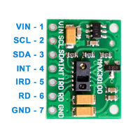
Mô tả các chân kết nối
| Thứ tự chân | Ký hiệu | Loại | Mô tả |
|---|---|---|---|
| 1 | VIN | Power | Nguồn cấp 1.8V - 5.5V (khuyên dùng 5V) |
| 2 | SCL | Input | I2C SCL |
| 3 | SDA | I/O | I2C SDA |
| 4 | INT | Output | Chân INT của MAX30100 |
| 5 | IRD | Chân IR_DRV của MAX30100 | |
| 6 | RD | Chân R_DRV của MAX30100 | |
| 7 | GND | Power | Điện áp đất 0V |
Sử dụng với Arduino
Kết nối module với Arduino
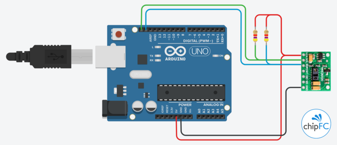
Kết nối cơ bản giữa module MAX30100 và Arduino như hình bên dưới. Chú ý là cần mắc 2 điện trở 4.7KΩ kéo lên cho hai đường SCL và SDA của I2C.
Tải thư viện
Dùng thư viện Arduino-MAX30100 library được phát triển bởi oxullo
Nếu bạn chưa biết cách sử dụng một thư viện Arduino có thể xem hướng dẫn tại Thư viện Arduino
Sử dụng ví dụ mẫu
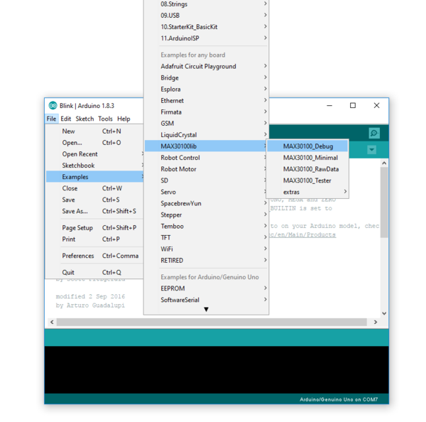
Sau khi cài đặt thành công thư viện Arduino-MAX30100, Arduino IDE sẽ xuất hiện mục MAX30100lib.
Với các Example được viết sẵn là:
- MAX30100_Debug: được dùng kết hợp với Processing pde "rolling_graph" (thư mục extras), để hiển thị dữ liệu với nhiều giai đoạn xử lý khác nhau.
- MAX30100_Minimal: một ví dụ đơn giản hiển thị kết quả dễ đọc qua Serial Monitor.
- MAX30100_DrawData: ví dụ lấy dữ liệu gốc từ cảm biến, chưa qua xử lý, có thể quan sát kết quả qua Serial Plotter hoặc Serial Monitor.
- MAX30100_Tester: sketch này giúp bạn tìm nguyên nhân gây ra lỗi cảm biến trong trường hợp cảm biến gặp vấn đề.
Thử với MAX30100_Minimal
Nội dung code mẫu
#include <Wire.h>
#include "MAX30100_PulseOximeter.h"

#define REPORTING_PERIOD_MS     1000

// PulseOximeter is the higher level interface to the sensor
// it offers:
//  * beat detection reporting
//  * heart rate calculation
//  * SpO2 (oxidation level) calculation
PulseOximeter pox;

uint32_t tsLastReport = 0;

// Callback (registered below) fired when a pulse is detected
void onBeatDetected()
{
    Serial.println("Beat!");
}

void setup()
{
    Serial.begin(115200);

    Serial.print("Initializing pulse oximeter..");

    // Initialize the PulseOximeter instance
    // Failures are generally due to an improper I2C wiring, missing power supply
    // or wrong target chip
    if (!pox.begin()) {
        Serial.println("FAILED");
        for(;;);
    } else {
        Serial.println("SUCCESS");
    }

    // The default current for the IR LED is 50mA and it could be changed
    //   by uncommenting the following line. Check MAX30100_Registers.h for all the
    //   available options.
    // pox.setIRLedCurrent(MAX30100_LED_CURR_7_6MA);

    // Register a callback for the beat detection
    pox.setOnBeatDetectedCallback(onBeatDetected);
}

void loop()
{
    // Make sure to call update as fast as possible
    pox.update();

    // Asynchronously dump heart rate and oxidation levels to the serial
    // For both, a value of 0 means "invalid"
    if (millis() - tsLastReport > REPORTING_PERIOD_MS) {
        Serial.print("Heart rate:");
        Serial.print(pox.getHeartRate());
        Serial.print("bpm / SpO2:");
        Serial.print(pox.getSpO2());
        Serial.print("% / temp:");
        Serial.print(pox.getTemperature());
        Serial.println("C");

        tsLastReport = millis();
    }
}
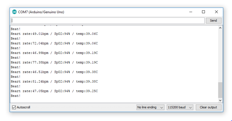
Sau khi Upload thành công lên Arduino, hãy thử mở Serial Monitor (menu Tools) để xem kết quả.
- Serial Monitor
Thử với MAX30100_DrawData
Nội dung code mẫu
#include <Wire.h>
#include "MAX30100.h"

// Tweakable parameters
// Sampling and polling frequency must be set consistently
#define POLL_PERIOD_US                      1E06 / 100
#define SAMPLING_RATE                       MAX30100_SAMPRATE_100HZ

// The LEDs currents must be set to a level that avoids clipping and maximises the
// dynamic range
#define IR_LED_CURRENT                      MAX30100_LED_CURR_50MA
#define RED_LED_CURRENT                     MAX30100_LED_CURR_27_1MA

// The pulse width of the LEDs driving determines the resolution of
// the ADC (which is a Sigma-Delta).
// set HIGHRES_MODE to true only when setting PULSE_WIDTH to MAX30100_SPC_PW_1600US_16BITS
#define PULSE_WIDTH                         MAX30100_SPC_PW_1600US_16BITS
#define HIGHRES_MODE                        true


// Instantiate a MAX30100 sensor class
MAX30100 sensor;
uint32_t tsLastPollUs = 0;

void setup()
{
    Serial.begin(115200);

    Serial.print("Initializing MAX30100..");

    // Initialize the sensor
    // Failures are generally due to an improper I2C wiring, missing power supply
    // or wrong target chip
    if (!sensor.begin()) {
        Serial.println("FAILED");
        for(;;);
    } else {
        Serial.println("SUCCESS");
    }

    // Set up the wanted parameters
    sensor.setMode(MAX30100_MODE_SPO2_HR);
    sensor.setLedsCurrent(IR_LED_CURRENT, RED_LED_CURRENT);
    sensor.setLedsPulseWidth(PULSE_WIDTH);
    sensor.setSamplingRate(SAMPLING_RATE);
    sensor.setHighresModeEnabled(HIGHRES_MODE);
}

void loop()
{
    // Using this construct instead of a delay allows to account for the time
    // spent sending data thru the serial and tighten the timings with the sampling
    if (micros() < tsLastPollUs || micros() - tsLastPollUs > POLL_PERIOD_US) {
        sensor.update();
        tsLastPollUs = micros();

        Serial.print(sensor.rawIRValue);
        Serial.print('\t');
        Serial.println(sensor.rawRedValue);
    }
}
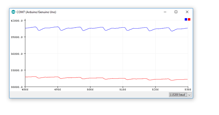
Sau khi Upload thành công lên Arduino, hãy thử mở Serial Plotter (menu Tools) để xem kết quả.
- Serial Plotter
Chú ý
- Cảm biến được tối ưu để đo chính xác nhất ở đầu ngón tay. Đặt đầu ngón tay lên cảm biến (che 2 LED trên cảm biến) khi đo.
- Khi cảm biến hoạt động, sẽ có một trong 2 LED trên cảm biến sáng màu đỏ.
